I started by looking over the original engine which although complete did not have any spark plugs fitted, apparently an attempt was made some years before I bought the car to free up a light seizure due to standing, unfortunately the plugs were not put back after the initial inspection so further corrosion occurred. See the images below to see the story unfold
As part of the deal I had with car I got a later 110 engine, this was as removed from a 406 and was not seized. After much thought and discussion with those in the know I decided to use the 110 engine with a view sorting out the original 100A engine at a later date. As I took the 110 engine apart various issues came to light, the main one being a well worn crank and a cracked rear bearing cap. The main bearing clearance had opened up such that the oil scroll at the flywheel end of the crank had picked up on the main bearing cap and caused blueing and a hairline crack. The crank was already at -010 (well more like -0115) so had already seen a rebuild and this was further apparent when I encountered a non standard nut on one of the bigend caps, someone had managed to force a unf nut onto one of the studs!
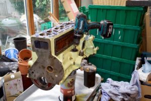
PICS OF DISMANTLING
This all made me wary of anything else on the engine. As this was the first time I’d seen the entrails of a 6 cylinder engine I thought it wise to give the whole lot to Hurley engineering to advise on what was worn and what could be salvaged, to cut a long story short anything that went up and down or round and round was re-ground, bored, replaced.
PICS OF NEW BITS
Further inspection of the entrails saw some marks on the oil spinner that is sited between the cam sprocket and the front timing chain housing. The timing chain, or rather the split link that protrudes slightly, was cutting its way into the oil spinner, I made a mental note to fit the split link such that the clip side is to the back of the sprocket or better still use an endless chain.
PIC OF OIL SPINNER
I finally got to the bottom of why the crank was so badly worn in comparison to everything else, the square on the oil pump drive shaft that fits in the skew gear was well rounded as was the corresponding drive receptacle in the skew gear,so much show that there was no longer a positive drive to the pump. Had the oil pump seized perhaps? Nope, the pump looked fine, no marks/galling associated with possible seizure. The mystery of oil pump drive shaft failure was obvious when I compared with replacement shaft and skew gear from IN Racing, the original shaft was over half an inch shorter so just a small amount of shaft engaged in the skew and it eventually failed.
PICS of CRANK and OIL PUMP DRIVE
Rocker gear – Despite much trepidation reassembling the valve gear was straight forward. When I took it apart I noted the position of all the rockers and caps. There positions did not always match up with factory markings, this confirmed my concerns about care/observations of previous assembler as despite clear marking on the rocker shaft caps and rockers along with numbering stamped on the head itself the previous engine builder not only managed to misplace some of the rockers and caps but once discovering that some of caps did not line up they clumsily filed the caps to fit.
PICS of Rocker shaft
Checking Oil pump flow through galleries

Recent Comments