Engine restoration
I started by looking over the original engine which although complete did not have any spark plugs fitted, apparently an attempt was made some years before I bought the car to free up a light seizure due to standing, unfortunately the plugs were not put back after the initial inspection so further corrosion occurred.
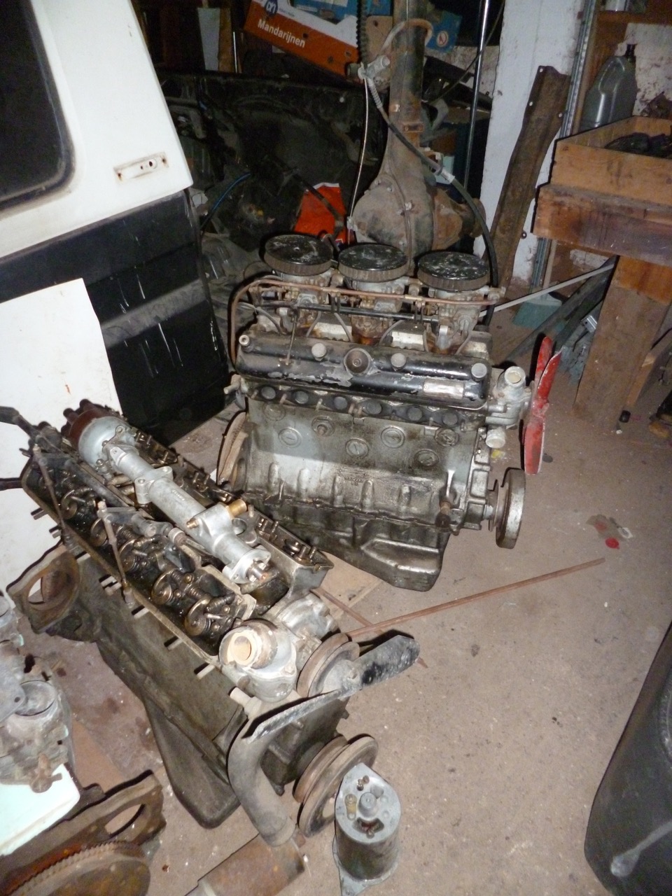
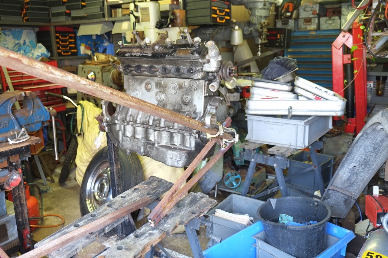
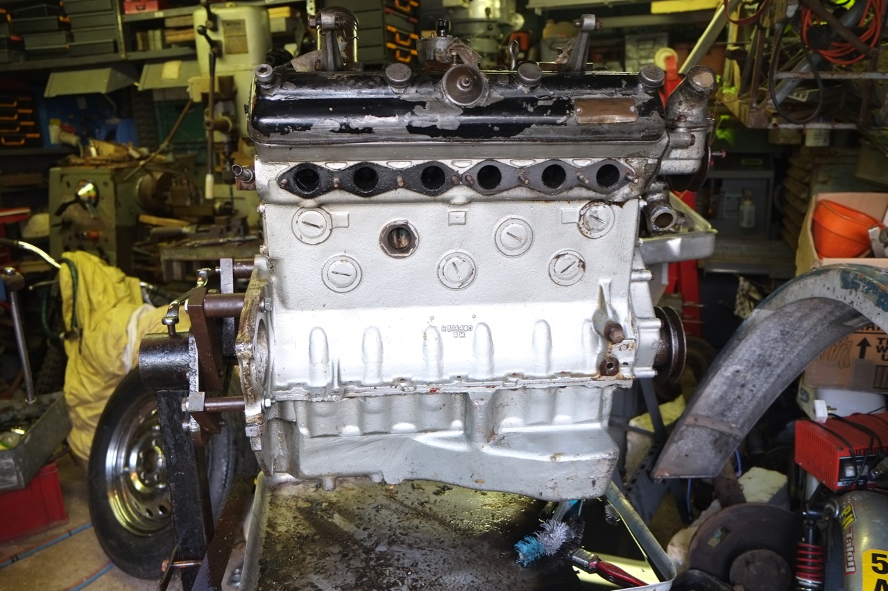
This all made me wary of anything else on the engine. As this was the first time I’d seen the entrails of a 6 cylinder engine I thought it wise to give the whole lot to Hurley engineering to advise on what was worn and what could be salvaged, to cut a long story short anything that went up and down or round and round was re-ground, bored, replaced.
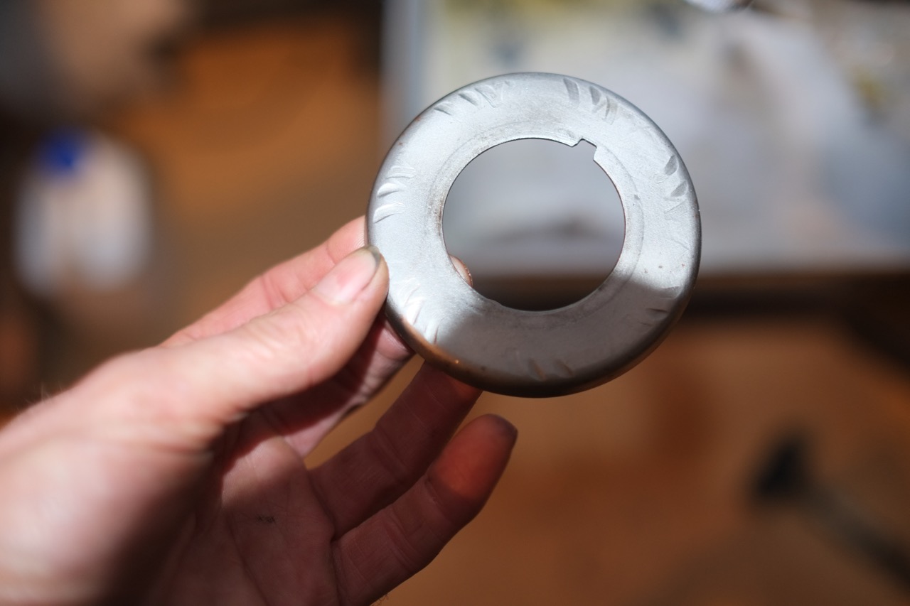
Further inspection of the entrails saw some marks on the oil spinner that is sited between the cam sprocket and the front timing chain housing. The timing chain, or rather the split link that protrudes slightly, was cutting its way into the oil spinner, I made a mental note to fit the split link such that the clip side is to the back of the sprocket or better still use an endless chain.
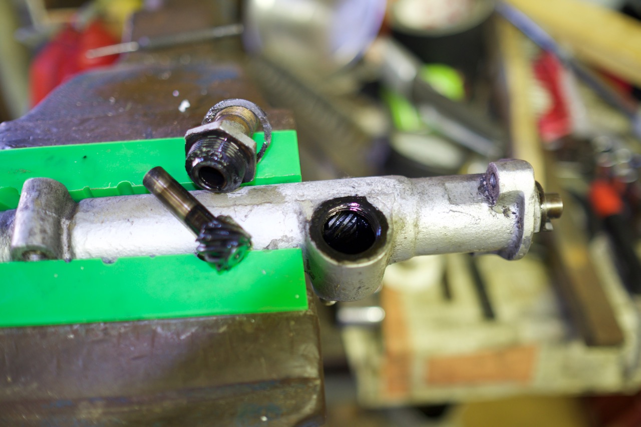
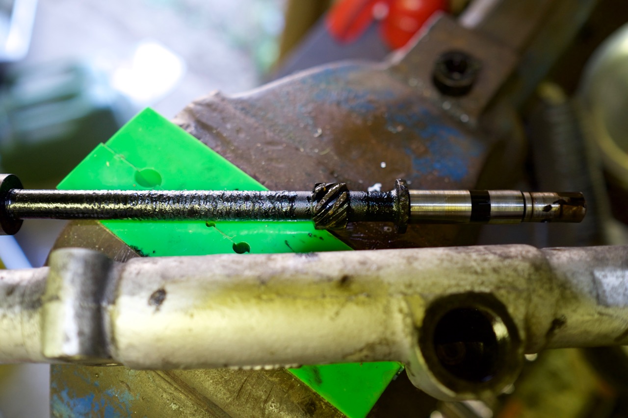
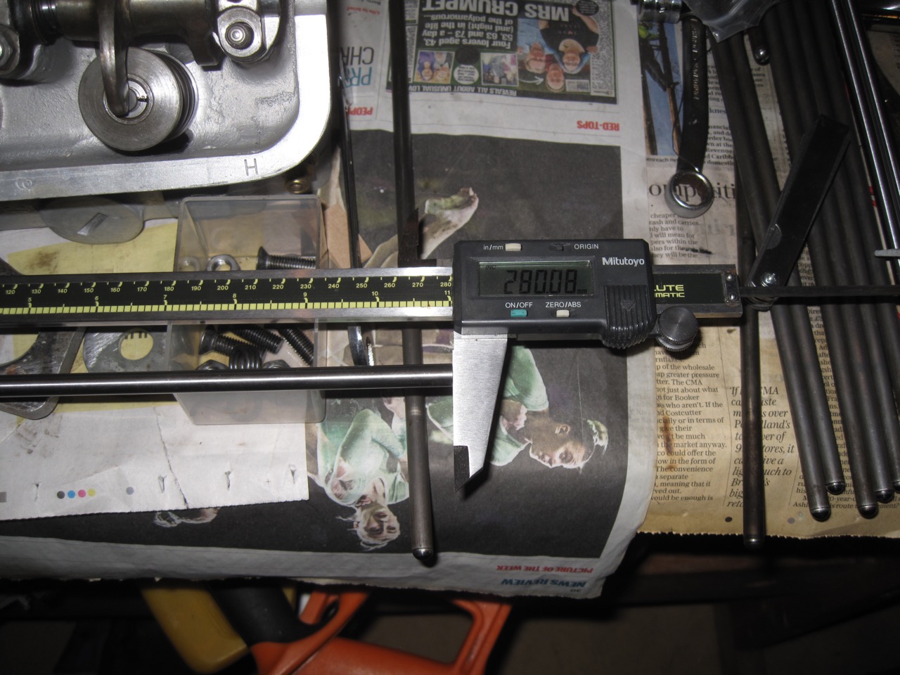
I finally got to the bottom of why the crank was so badly worn in comparison to everything else, the square on the oil pump drive shaft that fits in the skew gear was well rounded as was the corresponding drive receptacle in the skew gear,so much show that there was no longer a positive drive to the pump. Had the oil pump seized perhaps? Nope, the pump looked fine, no marks/galling associated with possible seizure. The mystery of oil pump drive shaft failure was obvious when I compared with replacement shaft and skew gear from IN Racing, the original shaft was over half an inch shorter so just a small amount of shaft engaged in the skew and it eventually failed.
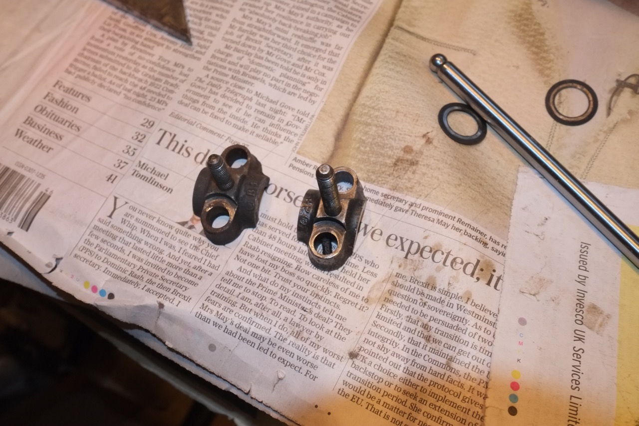
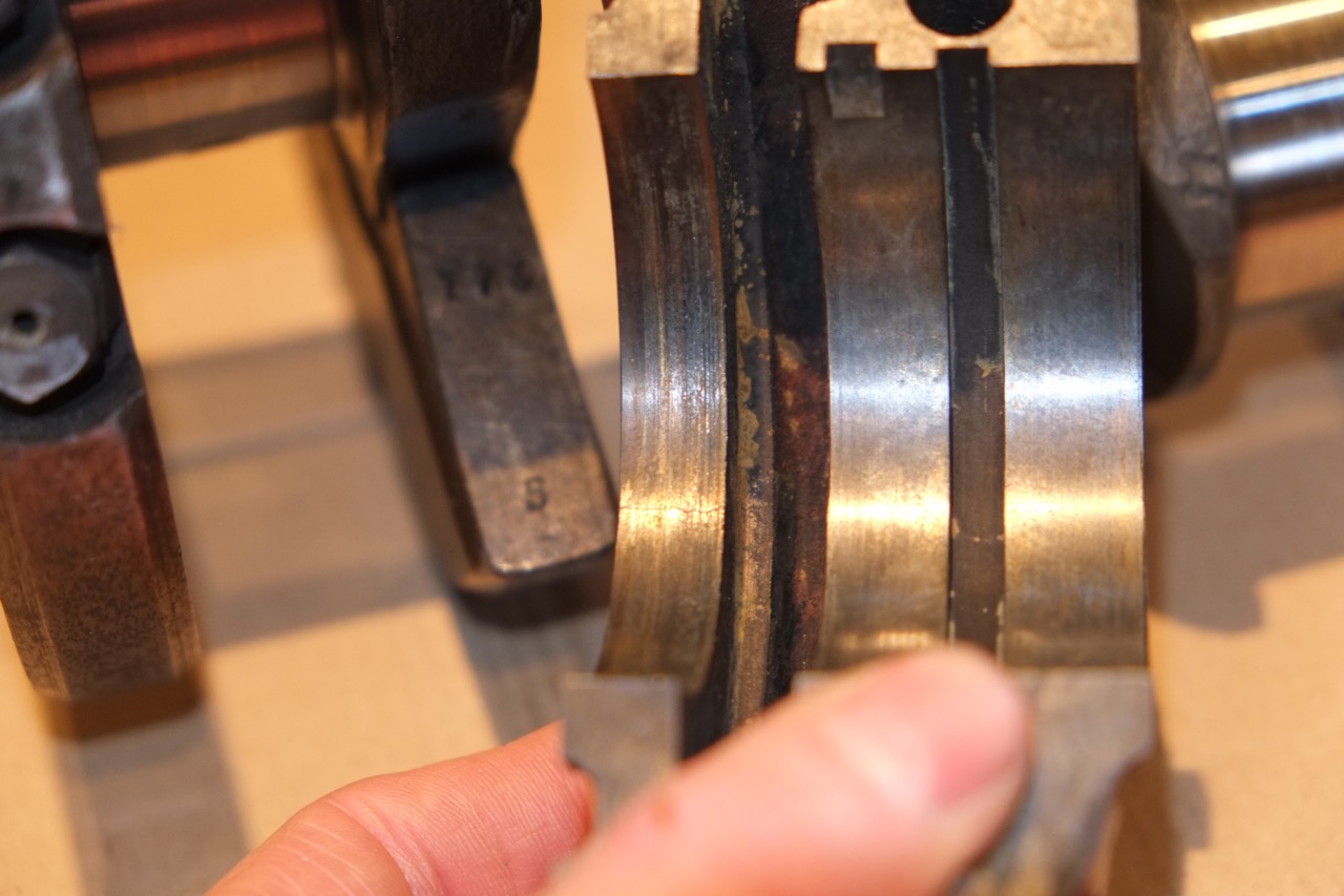
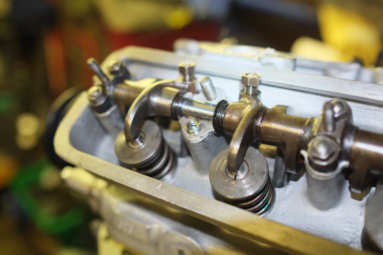
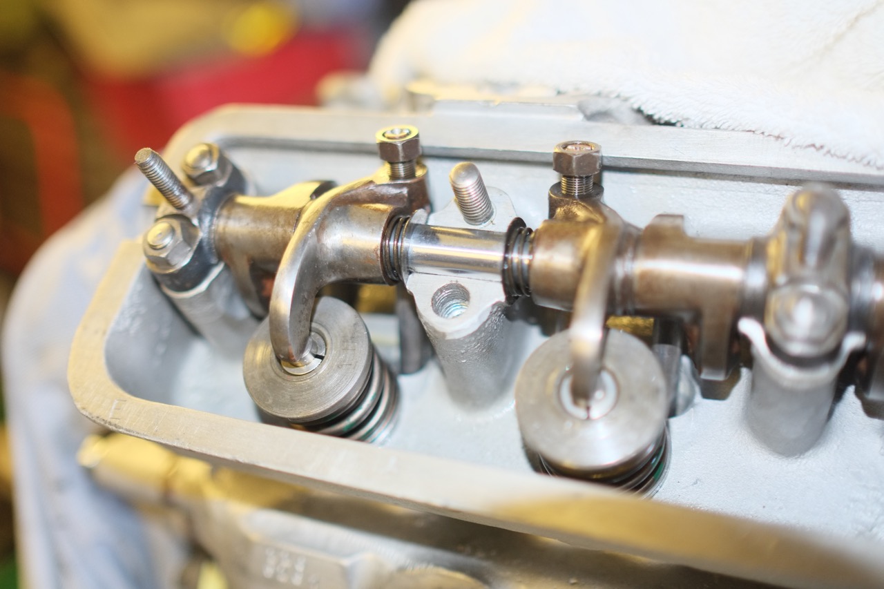
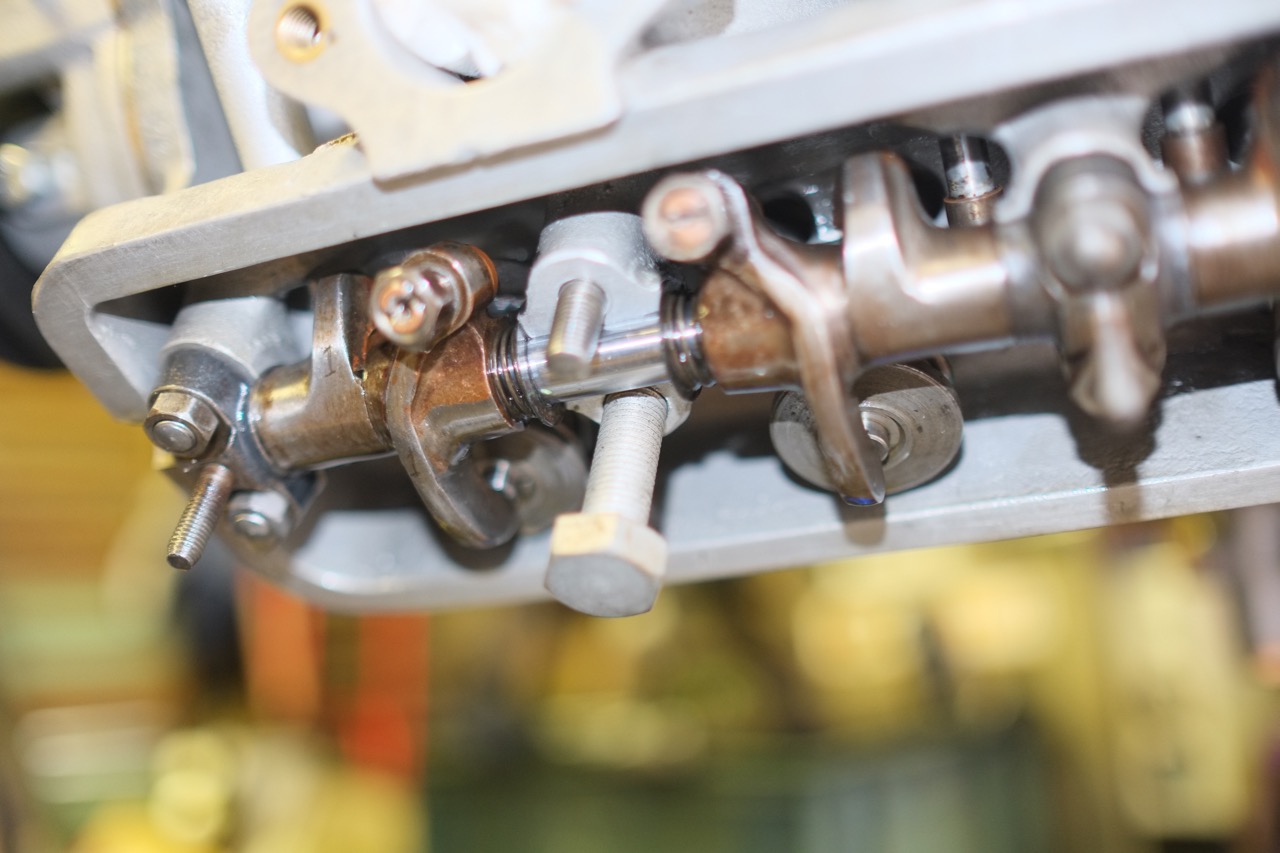
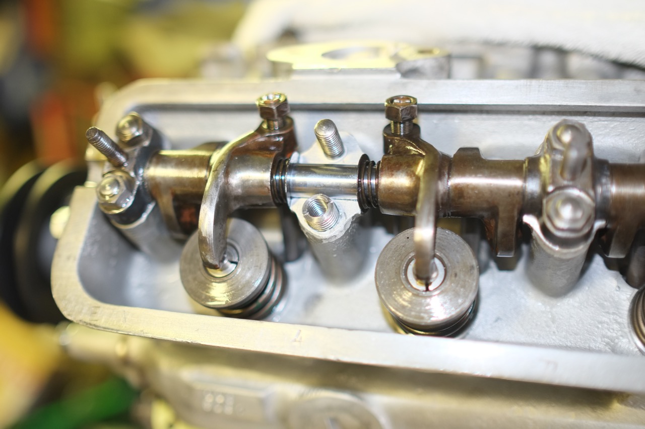
Rocker gear – Despite much trepidation reassembling the valve gear was straight forward. When I took it apart I noted the position of all the rockers and caps. There positions did not always match up with factory markings, this confirmed my concerns about care/observations of previous assembler as despite clear marking on the rocker shaft caps and rockers along with numbering stamped on the head itself the previous engine builder not only managed to misplace some of the rockers and caps but once discovering that some of caps did not line up they clumsily filed the caps to fit.
On dismantling the distributor tower I found the housing more or less solid with treacle like oil. No perceptible play in bushing however once cleaned up, just a case of checking end float of tacho drive once takeoff had been tightened up.
After recommendation I fitted a modern alternator, I heard from several sources that there had been issues with ones that look like dynamos so opted for a bog standard modern one (Lucas ACR17 type). Will treat the car to a ‘dynamo look’ alternator in due course once I’ve researched the different vendors and reliability. To fit the alternator I made a longer bottom bracket that attaches to the block and supports the rear of mounting lug of the alternator. Being determined to keep all the fastenings imperial I drilled out the existing M8 thread from the front mounting and helicoilded 5/16 whit. The original Dynamo pulley was fitted to the alternator, I only discovered late in the day that the original dynamo and new alternator shared a 15mm shaft, just needed to take some material off back of the pulley to facilitate line up with water pump and bottom pulley. I spent some time trying to obtain a pilot bore pulley with ‘B’ profile grove with a smaller diameter in order to increase the alternator speed. I wanted to fit a small pulley If a pulley less than around 80mm diameter (that being the dimension of the dynamo pulley) exists then I could not track one down. In order to get the pulley to line up I needed to take around ¼ of material from the inner boss, that was the maximum I could do before weakening the whole assembly. My focus was on pulley size and alignment so I missed the fact that the part of alternator casting was tight against the block such that I could not pivot the alternator up enough. I then discovered that the standard method was to move the pickup up points for the alternator away from the block by about an inch. Being in a rush I decided to take a hacksaw (thanks for the loan Rob) to alternator casting and managed to removed enough material to let the alternator swivel up using the existing pivot points. My original concern with the pulley size went away when I found that I had a 20amp charge at 1000rpm.
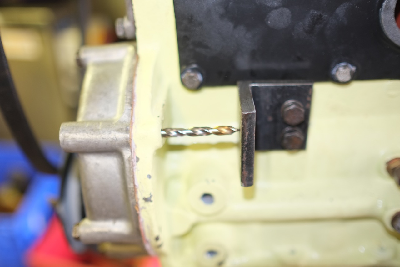
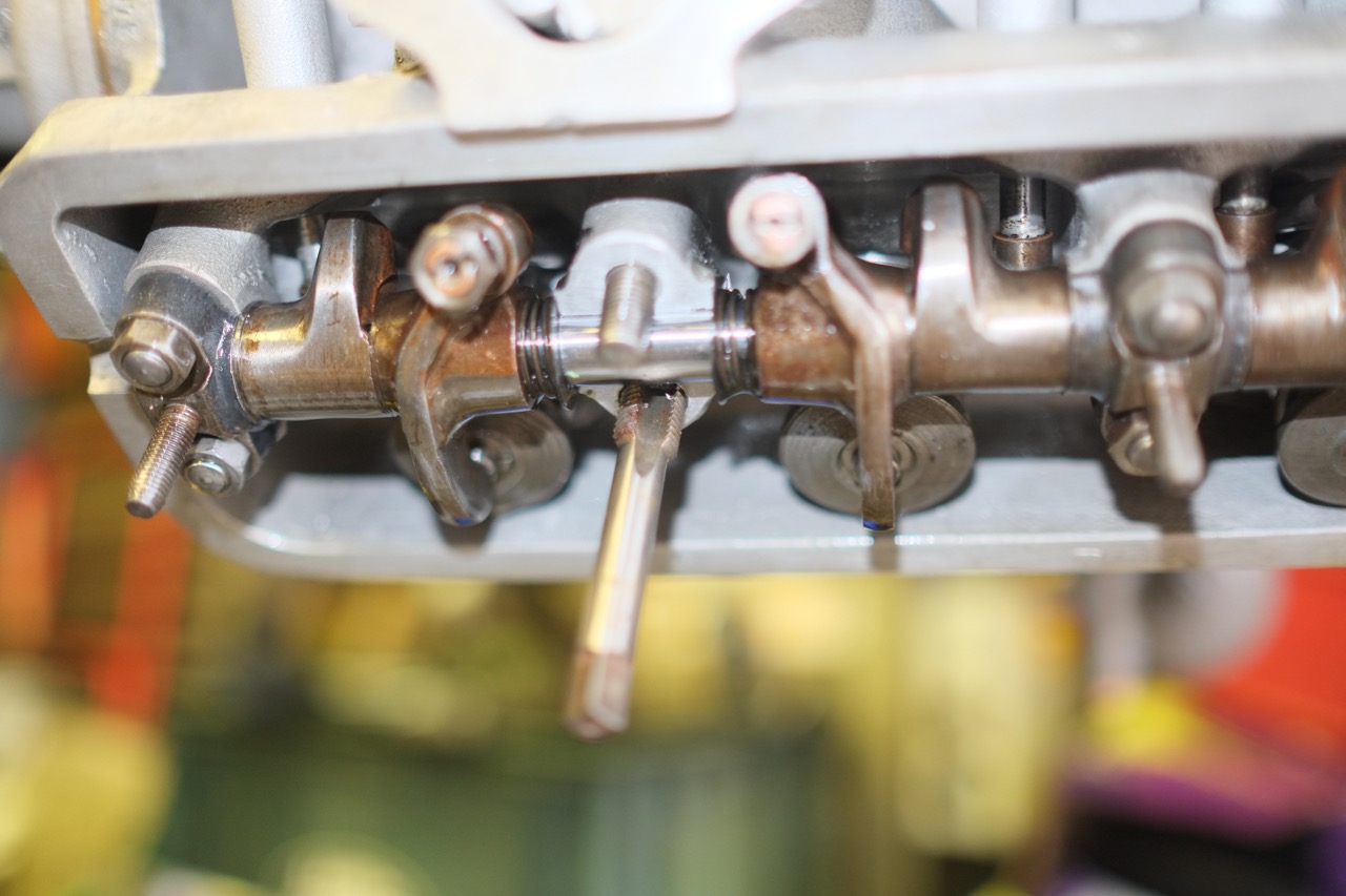
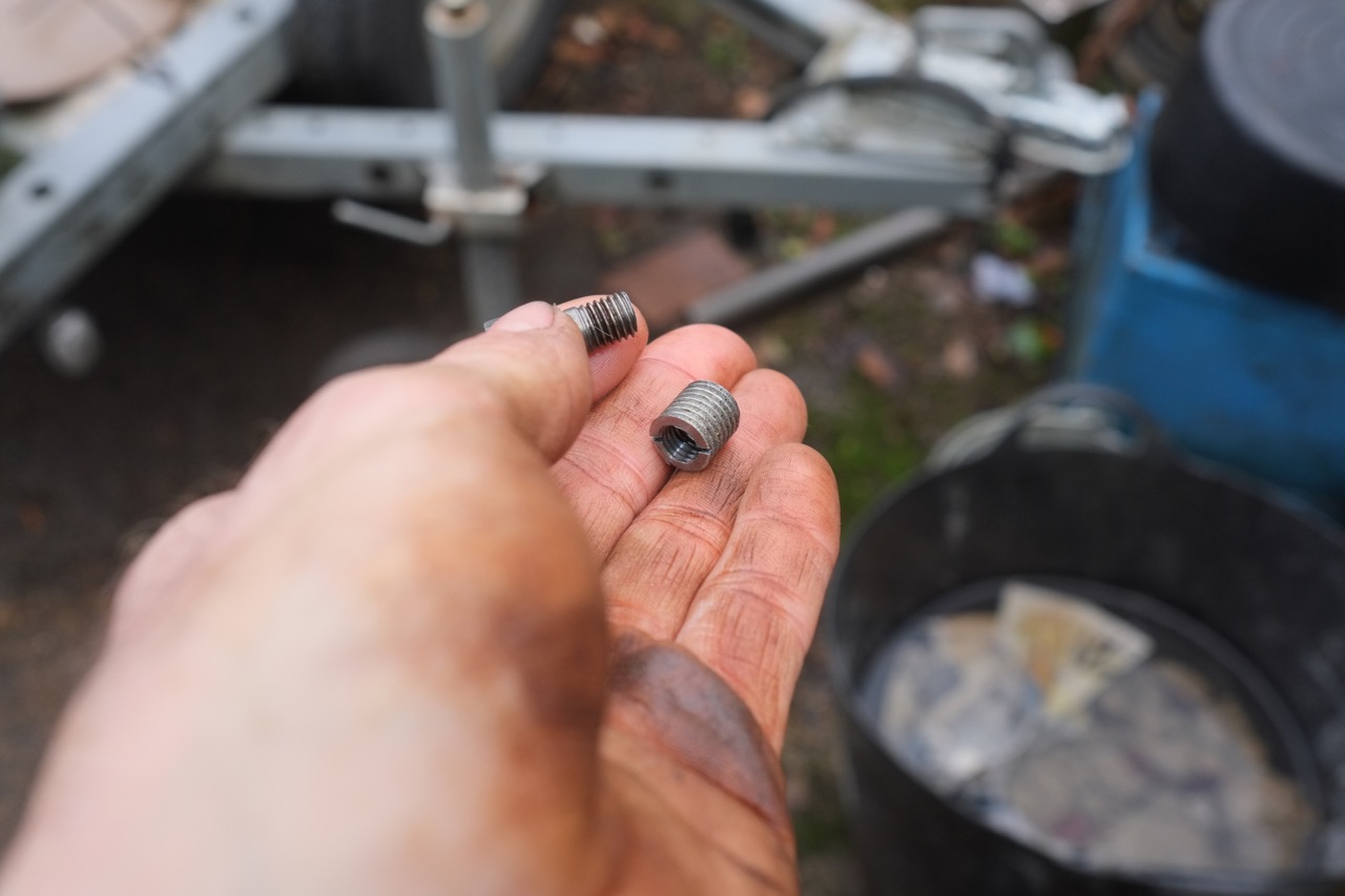
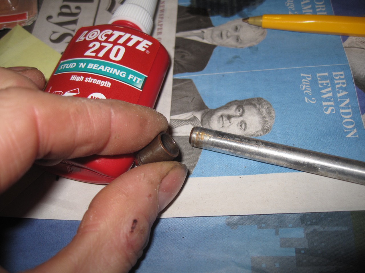
While tightening a rocker shaft cap a stud started to pull out of the head. Further inspection showed that the stud hole in the head had been helicoiled in the past and the helicoil had pulled out of the head. In order to make a fix an even larger hole was drilled to accommodate a 7/16 BSF insert which I made up from HT set bolt.
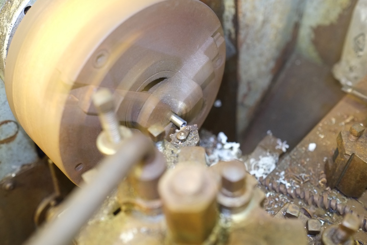
I went for a new Piper high torque cam (2 litre cam from IN racing) as part of the engine rebuild. The lobe spacing on the camshaft differs between 2 and 2.2 litre engines, yep I know now! The difference in spacing accommodates the different conrod offset compared to the 2 litre engine. A 2 lire cam in my 110 block resulted in the cam lobes just brushing the conrods when the crankshaft is pushed forward against the thrust bearing. The 2.2 litre cam which I had discarded in favor of the latest high torque offering could not be re-fitted as new cam bearings had been fitted to suit the 2 litre cam – the rear most journal is 20 thou smaller. Bristol made the rear journal a different size to stop the 2.2 litre cam being fitted to the 2 litre engine, no doubt to avoid cam lobe to conrod fouling!. Options were to A) have the rear most journal of the 2.2 litre cam ground down to suit, B) redo the cam bearings to suit the 2.2 lire cam. C) grind some material from the side of the lobes of the 2 litre cam. Option C was taken as it was by far the quickest but not necessarily the best solution…. Time will tell as to whether the offset of the lobe may result in spinning the cam follower more than standard setup.
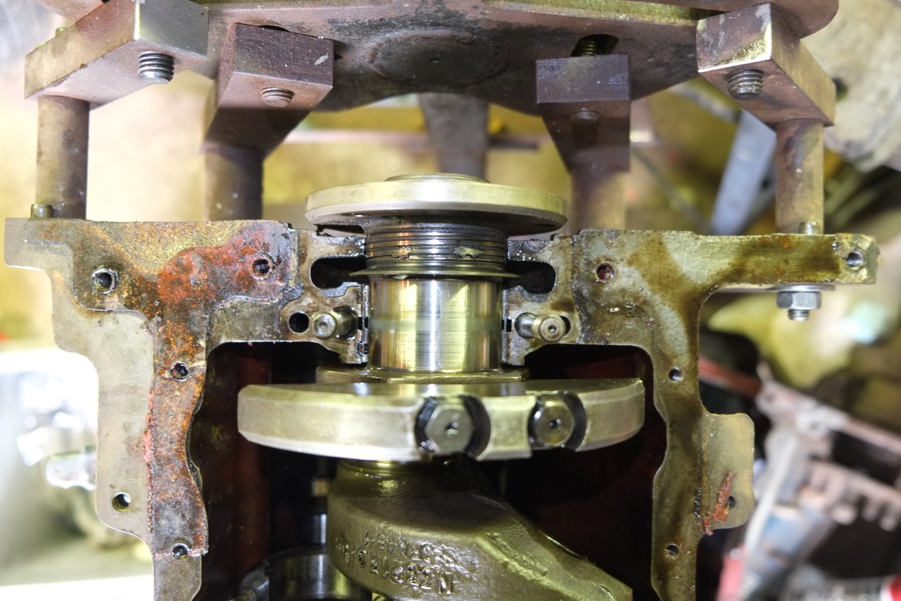
The timing cover was modified my Hurley engineering to take a modern oil seal. On initial assembly I had not taken into account the ‘top hat’ holding the modern seal protruded into the housing, I discovered this though when I refitted the timing cover and found the oil spinner was touching the new housing. Material that previously formed a guard for the original felt seal was removed and the engine rotated freely again.
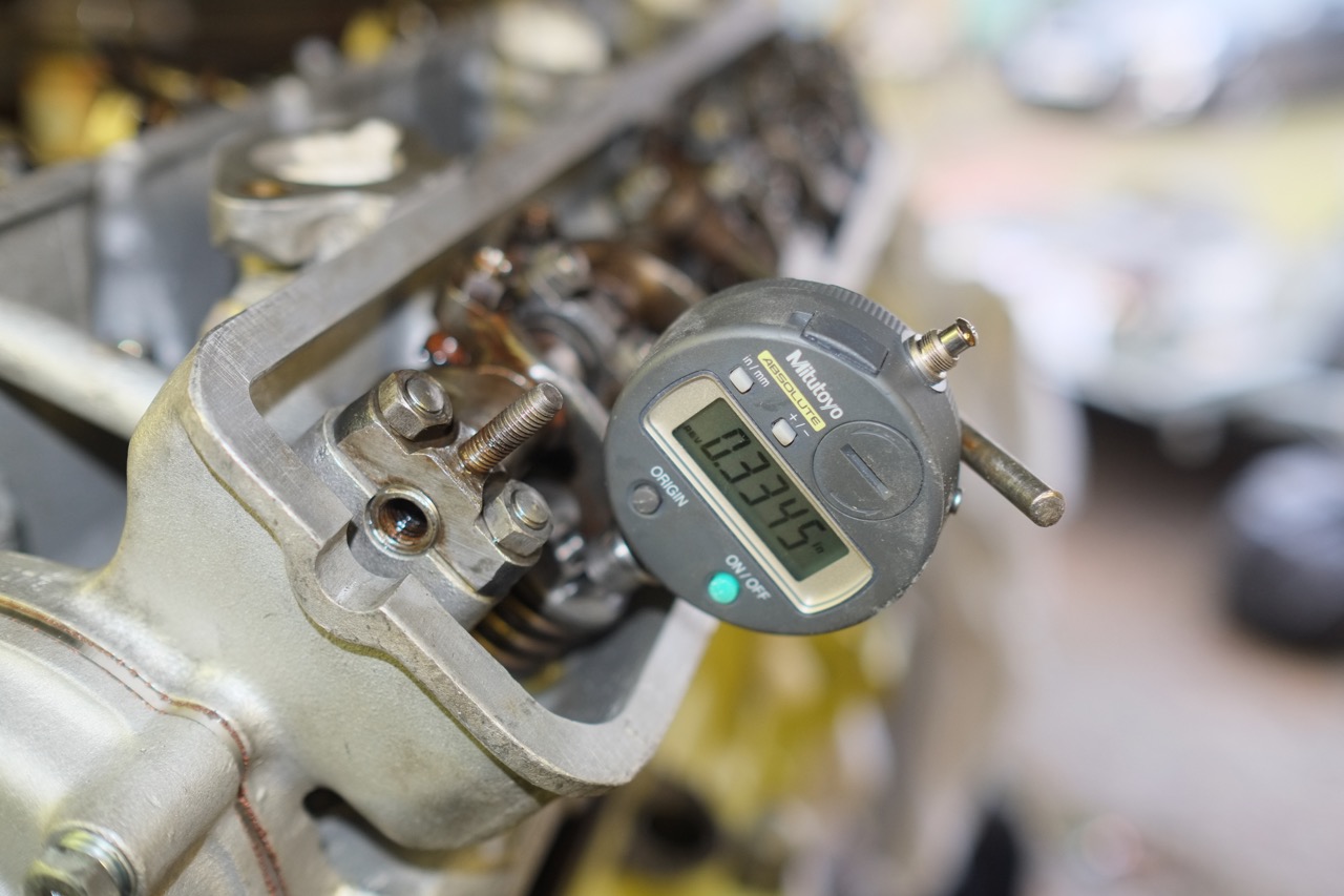
Valve timing – no matter what I tried I could not get the cam timing anywhere near what it should be with the original sprocket (110 at maximum lift). I reluctantly stumped up for an adjustable sprocket rather than going down the offset woodruff key method. I now gather that an adjustable sprocket is an inevitable purchase if you want to fit a 3rd party cam.
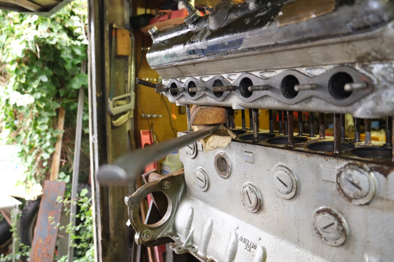
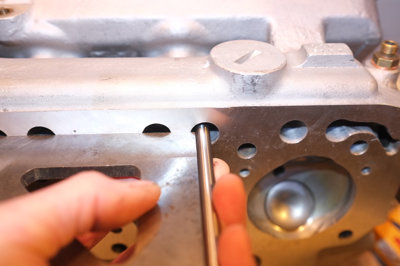
Several pushrods were bent, the bent ones had marks that coincided with the narrowest part of the pushrod holes in the block just below the deck. The random assembly of the valve gear by the previous builder I think attributed to the top of pushrods being less than central/perpendicular. In order to avoid a re occurrence of them touching the pushrod tubes I took a small amount of material from the top of push rod holes in the block and made sure that the rocker sat perpendicular to the tappet, some of this was a slight compromise as perfectly vertical pushrod meant that the rocker did not always sit dead square of the valve stem. The bent pushrods were replaced with new ones from IN racing, I should have probably had a go at straightening the originals but played it safe and went for new ones, just needed shortening to suit.
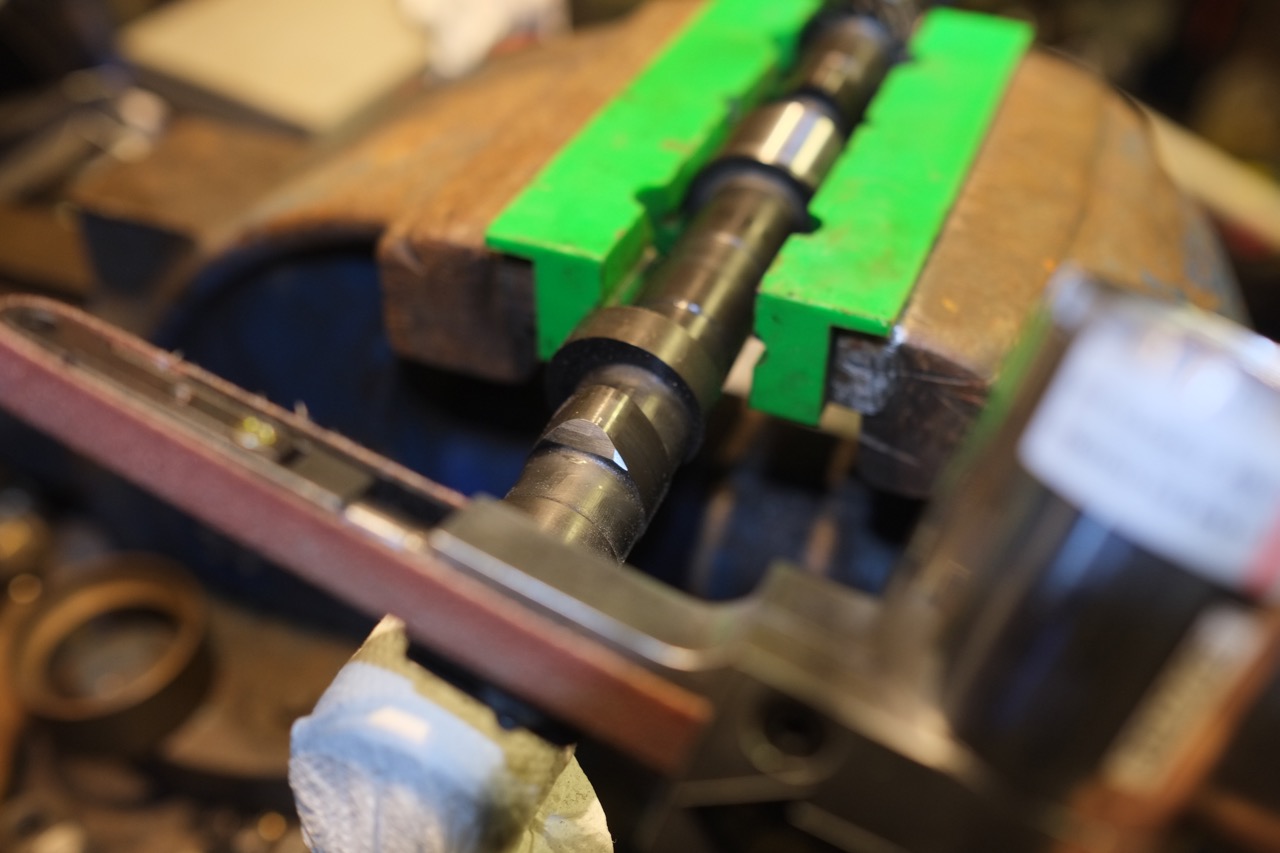
A click from the valve train….. Whilst turning over the engine to check timing I occasional heard a click from the valve gear. I mentioned this to Lee at SLJ and he immediately pointed me to underlying cause, the ball on the end of push rod gets a small pip on in over time, the pip coinciding with the hole in the corresponding rocker end cup. The noise occurred around half way through the valves travel as it was coming back onto the seat. The noise occurring as the pip on the pushrod slips into the small hole in the rocker cup. Solution, simply take the pip off the end of the pushrod by flatting the end on a fine abrasive until the pip is gone!